


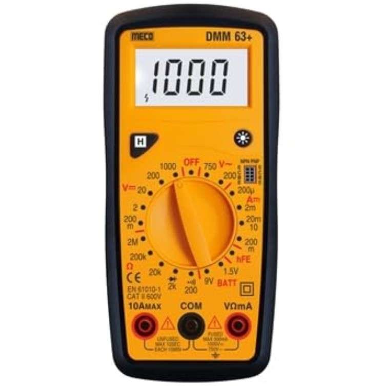


Meco DMM63+ Digital Multimeter
The Meco DMM63+ is a professional-grade digital multimeter designed for accurate measurement of voltage, current, and resistance across AC and DC circuits. Electrical technicians, field service engineers, and industrial maintenance professionals rely on this instrument to diagnose circuit faults, verify power supply integrity, and troubleshoot complex electrical systems. This multimeter solves the critical problem of quick and reliable electrical measurements in the field, eliminating guesswork and reducing downtime during equipment repairs and installations.
Product Overview
The Meco DMM63+ operates on the principle of digital signal conversion, where analog electrical parameters are sampled and converted to precise digital readings displayed on a high-contrast LCD screen. The device features a dual-range measurement capability that automatically selects the appropriate scale for optimal accuracy, minimizing user error and ensuring consistent results across varying voltage and current levels. The internal circuitry includes precision resistor networks and operational amplifiers that provide excellent linearity and minimal measurement drift across temperature variations, making it suitable for both laboratory and field environments.
What distinguishes the DMM63+ in the market is its robust construction with reinforced test lead connections, enhanced input protection circuits that safeguard against accidental overload conditions, and a user-friendly interface that accommodates both experienced technicians and trainees. The multimeter incorporates a true RMS measurement capability for AC voltage and current, ensuring accurate readings even with non-sinusoidal waveforms commonly found in variable frequency drive systems and switching power supplies. Its compact form factor and ergonomic design allow single-handed operation in confined spaces, while the backlit display provides visibility in low-light industrial environments.
Key Specifications
Key Features
- True RMS AC measurement capability for accurate readings on non-linear loads and variable frequency drives without harmonic distortion errors
- Automatic range selection with manual override option, reducing measurement time and eliminating the need for range guessing in field applications
- Overload protection circuits rated for 1000V on all input terminals, preventing internal component damage from accidental high-voltage exposure
- Backlit LCD display with 3.5-digit resolution showing 1999 counts maximum, enabling clear visibility in dimly lit industrial environments and underground installations
- Diode testing function with forward voltage measurement capability, essential for power electronics troubleshooting and semiconductor device verification
- Continuity buzzer with adjustable sensitivity threshold, allowing quick identification of open circuits and connection integrity without visual confirmation
Applications and Use Cases
- Industrial maintenance operations where technicians need to verify three-phase motor winding continuity, measure bearing temperatures via resistance changes, and diagnose power distribution faults in manufacturing plants
- Electrical installation and commissioning projects requiring voltage verification across distribution boards, current measurement in feeder cables, and insulation resistance testing before equipment energization
- HVAC system troubleshooting where technicians measure compressor motor current draw, verify thermostat control voltages, and test capacitor functionality in air conditioning units
- Renewable energy system monitoring including solar panel voltage verification, inverter output current measurement, and battery bank health assessment in off-grid installations
- Automotive electrical diagnostics for alternator output voltage testing, battery voltage confirmation, and starter motor current draw measurement during vehicle repair procedures
How to Use
Begin by selecting your measurement function using the rotary selector dial on the front panel. For DC voltage measurement, rotate the dial to the DC voltage symbol and select an appropriate range, then connect the red probe to the positive terminal and black probe to the negative terminal of your circuit. For AC measurements, switch to the AC voltage position and note that the DMM63+ automatically handles the true RMS conversion for non-sinusoidal waveforms. Always ensure the test leads are properly inserted into the correct input terminals: the common terminal for the black lead, and either the voltage/resistance terminal or the current terminal for the red lead depending on your measurement type.
When measuring current, always connect the multimeter in series with the circuit under test, never in parallel, and ensure you select the appropriate current range before connecting to avoid damaging the internal shunt resistor. For resistance measurements, disconnect power from the circuit being tested to prevent false readings and potential damage to the multimeter. The continuity function emits an audible tone when resistance drops below approximately 50 ohms, making it ideal for tracing cables and identifying broken connections. Always remove the test leads after use and store the multimeter in a dry location, checking the battery level regularly through the low battery indicator on the display.


Reviews
There are no reviews yet.